BouffaloLabs Flash structure
Flashing Tools
Flashing and BouffaloLabs
Clocks
OpenOCD
Toolchains
Boards and Modules
Alternatives
BootRoms
JTAG on 16-19 BL61x
BouffaloLabs Flash structure
The Boot Header
At the start of the Flash, Bouffalolabs microcontrollers have a bootheader.
This bootheader provides configuration for the initialization of the MCU: Flash settings, boot address...
It's also accessed via the bootrom stored within ROM (128 kB at 0x21000000 on BL602) which will use it to perform checks (CRC of the data that has been flashed mostly).
Its structure and options are detailed in the python code of the flash tools (bflb-mcu-tool), as one option.
There is one option to disable CRC (CRC ignore bit set to 1) that appears to cause it to fail to boot and go waiting in the bootrom on the BL602 i tested it on.
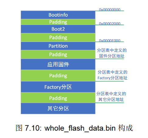
Organization Methods There are 2 ways to organize the flash in BL mcus:
The first one is the BFLB way, using a boot2 binary file provided with the SDK, a partition table is stored at a defined address, the bootheader is set to run the code of boot2,
which will proceed with checks and loading of various data.
This method is used if you use the SDK, which will generate the configuration for flashing.
The second one is the traditional way, the bootheader is set to jump to a specific address in the flash (0x2000 by default), and running the code from there.
<bflb_mcu_tool> --chipname=bl602 --port=/dev/ttyUSB0 --baudrate=115200 --firmware="helloworld_bl602.bin"
If you use bflb_mcu_tool, the bootheader will be parametred correctly without intervention and there is no additional verifications(beside the ones from the bootrom, configured via the bootheader) enabled.
Flashing Tools
Do not use the flash tool provided in the SDK!
Up to Date BLFlashCube and accompanying tools (command line versions), can be obtained from here: https://dev.bouffalolab.com/download
But the best tool, is the open source of version of it: https://pypi.org/project/bflb-mcu-tool/
Also installable via pypi and a Archlinux AUR package, be careful with the dependencies which you might need to fix manually, but it otherwise works fine.
pip install bflb-mcu-tool
I have found several other available options either dont do the operations correctly (blflash) or do not work at all with BL602, I recommend not using anything but the open bflb-mcu-tool or the up to date official tool.
Flashing and BouffaloLabs
Flashing a custom-built binary via UART is as simple as
<bflb_mcu_tool> --chipname=bl602 --port=/dev/ttyUSB0 --firmware="helloworld_bl602.bin"
But what happens is the following:
1. Initialization, core is running bootrom and reading bootheader
2. Bootrom detects flash mode is enabled because we are pull the relevant pin (GPIO8 on BL602) high, otherwise, continue initialization and jump to the defined address
3. Handshake with PC
4. Sideload flash tool in ram
5. Send some infos back(Flash Jedec ID), the PC will use those infos to build the boot header for the image to flash
6. Use Sideloaded tools to actually do the flashing
(7. Continue waiting for commands, this is not supported by most flash tools, you will be required to re-enter flash mode via buttons)
Clocks
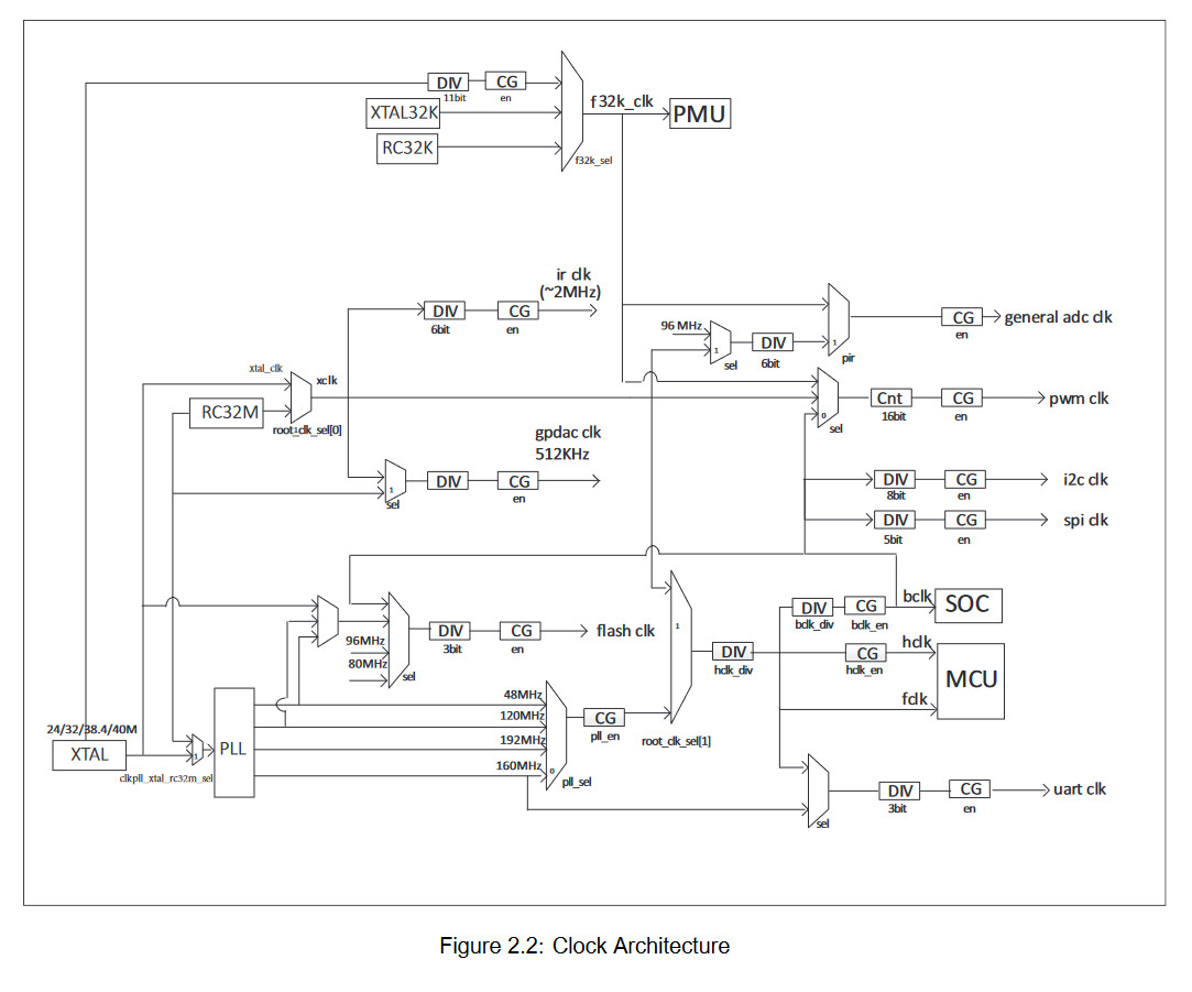
BFLB SoCs have adjustable clocks.
Most Relevant clocks are BCLK (peripheral clock), and HCLK/FCLK (CPU core clock).
the RISC-V architecture offers a cycle counter (mcycle) but also a CPU time counter (mtime). mtime frequency is a fixed 1MHz on BL602, while mcycle frequency is the current core frequency.
mtime is sometimes wrongfully used as a cycle counter (for example, in zephyr), and so the CPU frequency and cycle configuration numbers will not match reality.
It is possible to observe clock settings error by looking at the frequency of mtime, as misconfigured clocks will result in mtime not matching the right frequency.
On BL602, the clock settings are set in the clk_cfg0 sections of memory (0x40000000) and following addresses, see the reference manual.
To obtain the clock settings, it is possible to read those addresses, the bootheader may be configured to set a frequency at startup which may be different from defaults.
Additional informations (for example, the crystal frequency) are also accessible, examples for clocks are present in the SDK's driver files for this.
OpenOCD
Firstly, ensure you have a configuration file that is right for your adapter, here is one for a FT232H:
# tested on FT232HQ generic cheap purple adapter
Then ensure the connections to the device are right (the Datasheet or google will answer the pinout for a device).
# TCK: D0
# TDI: D1
# TDO: D2
# TMS: D3
# TRST: D4
# SRST: D5
adapter driver ftdi
ftdi vid_pid 0x0403 0x6014
ftdi tdo_sample_edge falling
ftdi channel 0
ftdi layout_init 0x0078 0x017b
ftdi layout_signal nTRST -ndata 0x0010 -noe 0x0040
ftdi layout_signal nSRST -ndata 0x0020 -noe 0x0040
adapter speed 1000
Secondly, ensure your device configuration file is right, there are some in the SDK.
Proceed with running openOCD, with the configuration files just mentionned:
openocd -f "ft232h.cfg" -f "bl602.cfg"
This should connect to your device and open a local socket for GDB to connect to.
Grab a gdb configuration file for your device, you might need to modify the port used, then run GDB with it: gdb -x "bl602.init"
Toolchains
Zephyr toolchains for RISC-V should work for everything afaik, just give it to the SDK.
The official toolchain should be fine otherwise, I believe what made it special has been mainlined a while ago.
Boards And Modules
Ai-Thinker
Ai-Thinker is a reliable provider of microcontroller modules, and has a set of Bouffalolabs Modules. I would recommend their modules in general.
Ai-WB2-* - BL602 Modules
Ai-WB2-12F - 12F (most common ESP8266 format) BL602 module, fits in lots of things designed for ESP8266
Ai-WB2-12F - 32S (most common ESP32 format) BL602 module, fits in lots of things designed for ESP32
Ai-M61-* BL618 Modules
Available in ESP-01, 32S, 32SU (32S without antenna) formats
Ai-M62-* BL616 Modules
Available in 12F, 32S, '13', and 'M2' formats
Rd-01 BL602 Module
Weird module with S3KM111L on it
Pine64
Pine64 is a maker of electronic products with strong interest in open source.
Pinenut - BL602 Modules
12S (12F without the bottom-side pins) and ESP-01S format.
Pinecone - BL602 Evaluation Board
USB C devboard that hosts a 12S module.
Ox64 - BL808 Board
Uses SDCard, Available with 2MB or 16 MB Flash, pi pico format
Sipeed
Sipeed is a maker of electronic products also leaning toward open source and RISC-V things.
M0 Sense - BL702 Board
Simple board.
M0S - BL616 Stamp Module
Tiny module for BL616
M0S - BL616 Stamp Board
Simple board to mount the stamp, built like a RV Debugger
RV Debugger - BL702 JTAG adapter / Secret Devboard
A small and cheap UART + JTAG adapter, also a BL702 devboard in times of need
M1S - BL808 Module
A castellated module for BL808
M1S Dock - BL808 Board
Uses a microSD,comes with camera connector and other options, a nice shell is available.
Alternatives
TG7100C is a alternative BL602 package, documentation for it is not available in english, but is available on baidu Datasheet
It is available in the Ai-Thinker TG-12F module.
JTAG on 16-19 BL61x
On some BL61x (Ai-Thinker M61), the normal JTAG 0123 mapping doesnt work. It is possible to switch the mapping to 16 17 18 19 by burning a efuse.
The procedure is as follow:
The simplest way to do this is using bouffalolab devcube, this will be explained, but the other tools can do it as well. This has the potential of permanently bricking your device if done improperly.
1. Make Efuse image and its mask, provided for convenience in there: Efuses Files
They are composed of 2 elements, the efuse bin, which sets the value (0x96 at 0x5D here), and efuse_mask bin, which sets the modification mask (we only want to modify a single bit, so we put 0x4 at 0x5D.
2. Copy the 2 files to chips/bl616/efuse_bootheader/, overwrite if other files of same name are present.
3. Open Devcube, enable advanced pages, and go to the 'Efuse' tab.
4. Setup your settings on the right side and your device, do not click any buttons, especially program or create. Set AES Mode to None and verify no locks or keys are set.
5. Press the Program button.
6. Verify by resetting the device into flash mode, pressing the Read button, and opening the file efuse.bin next to devcube executable that 0x5D is now 0x96 instead of 0x92
Finally, it is possible JTAG will still not work depending on your bootrom version. If this is the case, you need to set in your program the AON control register enable to 0, as it is preventing using the pins.
To do this, set bits mask 0xF00000 in HBN_PAD_CTRL_0 (0x38 + 0x2000f000) to zero, eg HBN_PAD_CTRL_0 = HBN_PAD_CTRL_0 & ~0xF00000;
		tmp = sys_read32(HBN_BASE + HBN_PAD_CTRL_0_OFFSET);

tmp &= ~HBN_REG_EN_AON_CTRL_GPIO_MSK;

sys_write32(tmp, HBN_BASE + HBN_PAD_CTRL_0_OFFSET);
After this code has been executed, you should be able to connect to JTAG.